Every part in a cable joint kit, named
A GTJ/2436 box holds twenty numbered components and eight installation aids. This is what each one is, which kit it is counted in, and where the published record runs out.
A joint sheet is a bill of material in three parts
The manufacturer's joint sheets do not print a product description. They print a bill of material under three headings: Cable Components, Kit Components, and Installation aids & Accessories (Part of std. Kits). The first heading is not in the box. It is the cable in front of you, drawn and numbered so the kit items have something to be numbered against.
Mixing those two columns is how a schedule goes wrong. Armour, conductor, copper screen and inner sheath all carry callout numbers on a GTJ drawing. None of them ships.
Every sheet closes on the same note: all kits are supplied with full kit contents for making one joint. The manifest is exhaustive by design. On the list means in the box. American practice calls the same carton a splice kit and these parts cable splicing kit components, and nothing on the list changes with the spelling.
Eleven callouts on the GXLT drawing, and five of them are the cable
The GXLT/GPLT sheet numbers eleven callouts around a cutaway of a finished 1.1 or 3.3 kV joint. It prints no quantity against any of them. It is the one joint sheet in the range with no Qty column.
Read it across from the GTJ and GXS sheets, which do split their lists. Five of the eleven turn out to be cable, not kit. The same sheet's second drawing, for paper cable, runs to fourteen callouts; oil barrier tubing, inner protective tubing, a lead sheath and a plumb appear only there.
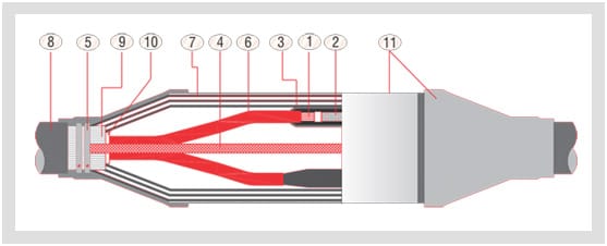
GXLT/GPLT callout key
| No. | Callout | Cable or kit? |
|---|---|---|
| 1 | Conductor (aluminium/copper) | Cable |
| 2 | Inline connector (ferrule) | Kit |
| 3 | Insulation sleeve | Kit |
| 4 | Armour continuity connection | Kit |
| 5 | Worm drive clamps | Kit |
| 6 | Cable insulated core | Cable |
| 7 | Wraparound joint case | Kit |
| 8 | Outer sheath | Cable |
| 9 | Cable armour | Cable |
| 10 | Inner sheath | Cable |
| 11 | Outer jacketing sleeves | Kit |
Callout names taken from the manufacturer's GXLT/GPLT sheet. The third column is not on that sheet — it is read across from the GTJ and GXS sheets, which do head their lists Cable Components and Kit Components. Our reading, not published.
GTJ/2436 kit components — the full manifest
| No. | Component | Qty. |
|---|---|---|
| 1 | Inline connector (barrier type) | 3 Nos. |
| 2 | Stress relief mastic | 6 Nos. |
| 3 | Heat-shrink oil barrier sleeve | 3 Nos. |
| 4 | Semi-conducting tubing | 1 No. |
| 5 | High permittivity void filler | 1 No. |
| 6 | Heat-shrink conducting breakout | 1 No. |
| 7 | Stress control mastic, at the semi-con cut end on the XLPE side and on the semi-conducting layer | 6 Nos. |
| 8 | Heat-shrink stress control tubing | 3 Nos. |
| 9 | Heat-shrink insulation tubings — 6 at 15–24 kV, 9 at 36 kV | 16 Nos. |
| 10 | Heat-shrink screened tubing (dual wall), or separate insulation and conducting tubings | 3 Nos. |
| 11 | Heat-shrink compression tubings | 3 Nos. |
| 12 | Metallic protection case / wraparound joint case, or GI mesh tape for mechanical protection | 1 No. |
| 13 | Heat-shrink adhesive-lined side sleeve | 2 Nos. |
| 14 | Insulating wedge, EPDM | 1 No. |
| 15 | Tinned copper mesh tape | 3 Nos. |
| 16 | Tinned copper earth braid | 1 No. |
| 17 | Constant force spring clamp, or solder and flux | 1 Set |
| 18 | Jubilee clamps | 2 Nos. |
| 19 | Heat-shrink outer jacketing tubing (centre) | 1 No. |
| 20 | Plumbing metal | 1 Set |
Names and quantities from the manufacturer's GTJ/2436 kV sheet, normalised for spelling only. Conductor area picks the box: GTJ-21 to GTJ-25 covers 25–500 sq mm at 15–24 kV, GTJ-31 to GTJ-34 covers 35–400 sq mm at 36 kV.
Item 9 does not agree with itself
The web page for GTJ/2436 names item 9 H. S. Screened Tubing, 16 Nos. The printed catalogue names it H. S. Insulation Tubings, 16 Nos. Both then name item 10 as the screened tubing. Neither explains how 16 squares with the 6 pieces at 15–24 kV and 9 at 36 kV printed underneath. The catalogue's name is used above. Get the count for your own voltage class confirmed in writing before this line reaches a tender.
Installation aids, and how they differ between two series
| Installation aid | GTJ/2436 | GXS/1236 |
|---|---|---|
| Nylon string for cutting XLPE insulation | 1 No. | 1 No. |
| Aloxite emery tape | 3 Pcs. | 3 Nos. |
| Mopping cloth | 1 Pc. | 1 No. |
| Silicone grease | 3 Pcs. | 3 Nos. |
| Cleaning tissue | 6 Pcs. | 6 Nos. |
| Mastic sealing tape | 2 Nos. | 1 Roll |
| Copper binding wire | 1 Roll | not listed |
| PVC adhesive tape | not listed | 1 Roll |
| Installation instruction manual | 1 No. | 1 No. |
Both sheets head this list Installation aids & Accessories (Part of std. Kits), so none of it is a separate order line. The GTJ web table's mopping-cloth cell is broken markup, quantity swallowed into the description; the figure above comes from the printed catalogue. GPS/1112 asterisks its aids inside the main numbered list instead, and adds cleaning solvent, PVC-Na tape and an emery sheet.
The inline connector, and the one step you cannot undo
Every joint in the range starts at the same item, and it sits at number 1 or 2 on every list. In GXLT, GXS and GXSS it is a plain crimping ferrule. GPS/1112 is the sheet that spells the material out — Inline Connector (Crimping Type) Ferrule Cu/al — so the ferrule matches the conductor, not the van stock. Three per kit on a three-core sheet, one on the single-core GXSS.
A GTJ kit does not use a plain ferrule. Both GTJ sheets list item 1 as an inline connector, barrier type, three per kit, with three heat-shrink oil barrier sleeves beside it. Paper cable is oil-impregnated and the oil travels. The barrier connector and the barrier sleeves stop it migrating out of the paper side into the XLPE side.
The crimp is the only irreversible operation in the box. Everything else is shrunk, wrapped, clamped or plumbed, and can be cut away and redone. A bad crimp also stays quiet. The GXLT type test runs 63 heating cycles in water — five hours heating, three hours cooling, 95 °C conductor temperature, no breakdown and no flashover. That is the test that finds a cold crimp. A joint that skips it finds one in service.
Everything in the box that is not a sleeve
- Stress relief and stress control mastic
- Hand-mouldable strip laid at the ferrule region and again at the semi-con cut end. Six pieces at GTJ item 2, six more at item 7; a GXS moves 6 to 9 with voltage class.
- Mastic sealing tape
- An installation aid rather than a component: one roll in a GXS/1236, two in a GTJ/2436.
- Constant force spring
- One set at GTJ item 17, printed as the alternative to solder and flux. The GXS sheet states it the other way round, three per kit.
- Worm drive clips
- Four per kit in a GXS/1236. Callout 5 on the GXLT drawing, with no quantity printed. Marked optional on the GPO/E sheets.
- Jubilee clamps
- Six in a GTJ/1112, two in a GTJ/2436. Same series, same part, three times the count at the lower voltage.
- Tinned copper earth braid
- One per kit. Item 16 on both GTJ sheets, item 13 on the GXS sheet, where it is labelled main earthing.
- Copper woven flexible mesh tape
- Three rolls in a GXS/1236, one roll in a GXSS. The GTJ sheets carry it as tinned copper mesh tape, three per kit.
- GI mesh
- One roll in a GXSS. On the GXS sheet a GI mesh application is the published substitute for item 11, the joint case.
- Wraparound metallic joint case
- One per kit: item 11 in a GXS, item 12 in a GTJ, callout 7 on the GXLT drawing.
- Insulating wedge, EPDM
- One per kit at GTJ item 14 and GPS/2436 item 13. GPS/1112 lists it at item 13 with no count, because that sheet prints none.
- Polymeric core separator
- GPS/1112 item 4, and nowhere else in the joint range.
- High permittivity void filler
- One per kit at item 5 on both GTJ sheets. GPS/2436 carries it at item 5 too, printed Void Foiler.
- Plumbing metal
- One set at GTJ item 20. On GPS/1112 it sits inside item 3 with copper braid, flux and binding wire, counted as one line.
- Glass cushion tape
- GPS/1112 item 6, and one roll on the GPO/E termination sheets. On no GXS, GXSS or GTJ joint list.
Four ways to read the same list
One column of names, four different jobs. The manufacturer's components index groups them by product family; a jointer groups them by what happens to them.
- Structural. Ferrule, sleeves and tubings, joint case, earth braid, outer jacketing sleeve. These stay in the ground for the life of the joint.
- Consumed. Emery tape, cleaning tissue, mopping cloth, nylon string, silicone grease, binding wire. Gone by the end of the shift, and still counted line items with quantities against them inside the standard kit.
- Voltage-dependent. A GXS/1236 carries 3 red insulating tubes at 12 kV and 6 at 24 and 36 kV; the mastics move 6 to 9. A GXSS carries 1 insulating tube at 12 and 24 kV, 2 at 36 kV.
- Alternatives, not extras. Where a sheet prints alternatively it means one or the other, never both. GI mesh instead of the joint case. Solder and flux instead of the constant force spring. Separate insulation and conducting tubings instead of the dual-wall screened tubing.
No source for these
Crimp tooling. The word crimp appears once in the manufacturer's joints catalogue, inside the name of the GPS ferrule. No die, no tonnage, no tool reference. Ferrule dimensions. Kits are ordered by conductor area, never by bore or barrel length, and neither is printed. Cut-back and setting-out lengths. The cross-sections are unscaled and carry no dimensions. Quantities on the GXLT/GPLT and GPS/1112 lists. Both number their parts; neither prints a Qty column. Storage. One line exists, in the catalogue's salient features: no shelf life limitations up to or below 50 °C. A temperature limit, not a dated life. This site stocks nothing and quotes nothing — all five are questions for the manufacturer.
The one place this list does not stretch
None of this applies to a bolted bar joint. A busbar splice is two flat bars, a bolt stack and a torque figure, insulated after the fact by something that comes off again for inspection. Nothing crimped, shrunk and plumbed shut. No busbar figure appears on this page, because no joint kit sheet in the range carries one. Busbar Sleeves, a reference published by the same team as Kit Sheet, covers the connection geometries and what covers each.
Count the box before you cut the cable
Do it in the van, not in the pit. Lay the manifest beside what came out of the carton and tick it off by item number, before a strand is cut. The sheets are explicit: one kit makes one joint. A short kit is unrecoverable on site — no second ferrule, no spare wedge, no extra length of red tubing.
Count against your voltage class, not the series on the label. Then check the code against conductor area — the size charts run series by series. GXS-13 and GXS-23 are the same three letters and a different cable.
After that it is order. Every sleeve goes on before the crimp, because afterwards none of them will pass the ferrule. That is the sequence page.
Where each part class is written up
- Sleeves and tubings, series by seriesRed insulating, stress control, screened dual wall, oil barrier, compression.
- Kit codes against conductor areaGXLT, GXS, GXSS, GPS and GTJ charts. Sq mm in, code out.
- The kit this manifest came out ofGTJ/1112 and GTJ/2436, paper one side, XLPE the other.
- What paper cable adds to the listOil barrier sleeves, the core separator, the plumb, the glass cushion tape.
- The other full three-core manifestGXS/1236: 13 kit components, 8 aids, 6 cable components to match.
- Which of these parts is usually the one that failedSix failure routes, and the manifest item each starts at.